Tesla Coil
Historical Background
Nikola Tesla (Smiljan, July 10, 1856-New York, January 7, 1943) was a physicist, inventor and engineer Serbian U.S.. He is best known for his revolutionary work and his many contributions in the field of electromagnetism in the late nineteenth and early twentieth centuries. His patents and his work formed the basis of modern alternating current electric power (AC), including the polyphase power distribution and the AC motor, with which he has 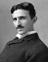 contributed to the birth of the second industrial revolution. His admirers go so far as to call it “the man who invented the twentieth century”. We know that this device operated by emitting electrons from the single electrode through a combination of field emission and thermionic emission. Once liberated, electrons are strongly repelled by the high electric field near the electrode during negative voltage peaks from the oscillating high voltage Tesla coil. Tesla experimented with a large variety of coils and configurations. He used to conduct innovative experiments on the electric light, the phenomena of alternating current and high frequency transmission of signals and power without wires.
Theoretical introduction
The Tesla coil is a device consisting of a transformer that uses electromagnetic induction to generate high frequency lightning very similar to those of atmospheric origin even if the amount is very small built for the first time by Nicola Tesla. It is a type of resonant transformer which consists of two coupled resonant circuits. A transformer Tesla coil operates in a manner different from a conventional transformer, in which the voltage gain is limited to the ratio of the numbers of turns of the coils. Otherwise, the voltage gain of a Tesla coil can be significantly larger. The coil transfers energy from an oscillating resonant circuit (the primary) to the other (the secondary). As soon as the primary transfers energy to the secondary, the voltage of the secondary production increases until all primary energy available was transferred to the secondary.
There are various types of coils tesla:
-Tesla Coil solid state: this type of coil is called “solid state” since it is controlled by an electric circuit without moving parts and without spark gap. The resonance frequency is generated directly by an electronic circuit. Tesla coils transistor using the operating voltage of the primary lower, typically between 175 to 800 volts and driving the primary coils using a bridge circuit to a half or a full bridge mosfet or bipolar transistor to switch the primary current.
-Tesla Coil Tube: for fans of the genre, these types of coils operate valves. To get exhausted really interesting and climb power, it is necessary to find huge military type valves such as GU81M in some specialized market or electronics fair. The particularity of the coils Tesla valve that is running at high frequency, make harmless discharges due to the skin effect, coils fed by thermionic valves typically operate with voltages between 1500 and 6000 volts, while most of coils spark gap operate with primary voltages of 6000 to 25 000 volts. The primary winding of a traditional transistor Tesla coil wraps only the lowest part of the secondary (sometimes called resonant).
-Tesla Coils-gap: this is the most common, which exploits the high frequency 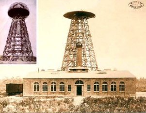 produced when the capacitor is discharged once loaded on the primary energy transferred to the secondary. The purpose in any case is to generate the primary winding a 3 frequence resonant with the secondary circuit, which must receive energy as a real antenna, transforming however to very high voltages, consequently decreasing the amperage. Even with a significant loss of electric shock well designed Tesla coil can transfer over 85% of the energy initially stored in the capacitor to the secondary circuit. The coils newer typically consist of a primary accumulation circuit that is a circuit composed of a high voltage capacitor, a spark gap, and a primary coil; And the secondary circuit, a series resonant circuit consisting of the secondary coil and the toroid .
The first reels
In the original design of Tesla for its largest coil, used a top terminal that consists of a metal frame in the shape of toroid, covered with smooth plates of metal in a semicircle (constituting a surface driver very large). In its largest complex Tesla employed this type of shaped element inside a dome. The upper terminal had a relatively small capacity, loaded with a voltage as high as possible. The outer surface of the upper terminal is where the electric charge accumulates. In the original plans of Tesla, the secondary LC circuit is composed of a coil loaded then placed in series with a large helical coil. The helical coil was then connected to the toroid. The majority of modern coils uses only a single secondary circuit. The toroid is in effect a terminal of a capacitor, the other terminal being grounded. The LC circuit is tuned to the primary so as to resonate at the same frequency of the LC circuit secondary. The primary and secondary coils are magnetically coupled, creating a resonant air-core transformer. The first Tesla coils needed large insulation to their connections to prevent discharges into the air. More recent versions of Tesla coils emit electric fields over large distances, thus allowing operations outdoors.
The coils modern
The most modern Tesla coils use simple toroids, typically constructed from metal wires or tubes bent aluminum, to control the high electric field near the top of the secondary target and discharges outside, away from the coils and primary secondarie. The Tesla coil is also famous for its ability to turn on the fluorescent tubes at a great distance without electrical connections. The modern Tesla coils, based on transistor or vacuum tubes, do not use a spark gap, but take advantage of the oscillations obtained directly from the transistor or vacuum tubes. The primary induces alternating voltage in the lower portion of the secondary, while offering “pushed” regular (similar to thrust properly calculated and provided in an oscillation of the field). Additional energy is transferred from the primary to secondary inductance and capacity of the upper terminal during each “push”, and secondary output voltage of production constitutes the upper ring of the apparatus. An electronic feedback circuit is usually used to synchronize the primary oscillator to the growing resonance in the secondary, and this is the only consideration tuning. The primary resonant circuit is formed by connecting a capacitor in series with the primary coil of the coil, so that the combination forms a series circuit with a resonant frequency close that of the secondary circuit. Because of the additional resonant circuit, are necessary manual adjustments and a tuning adaptive.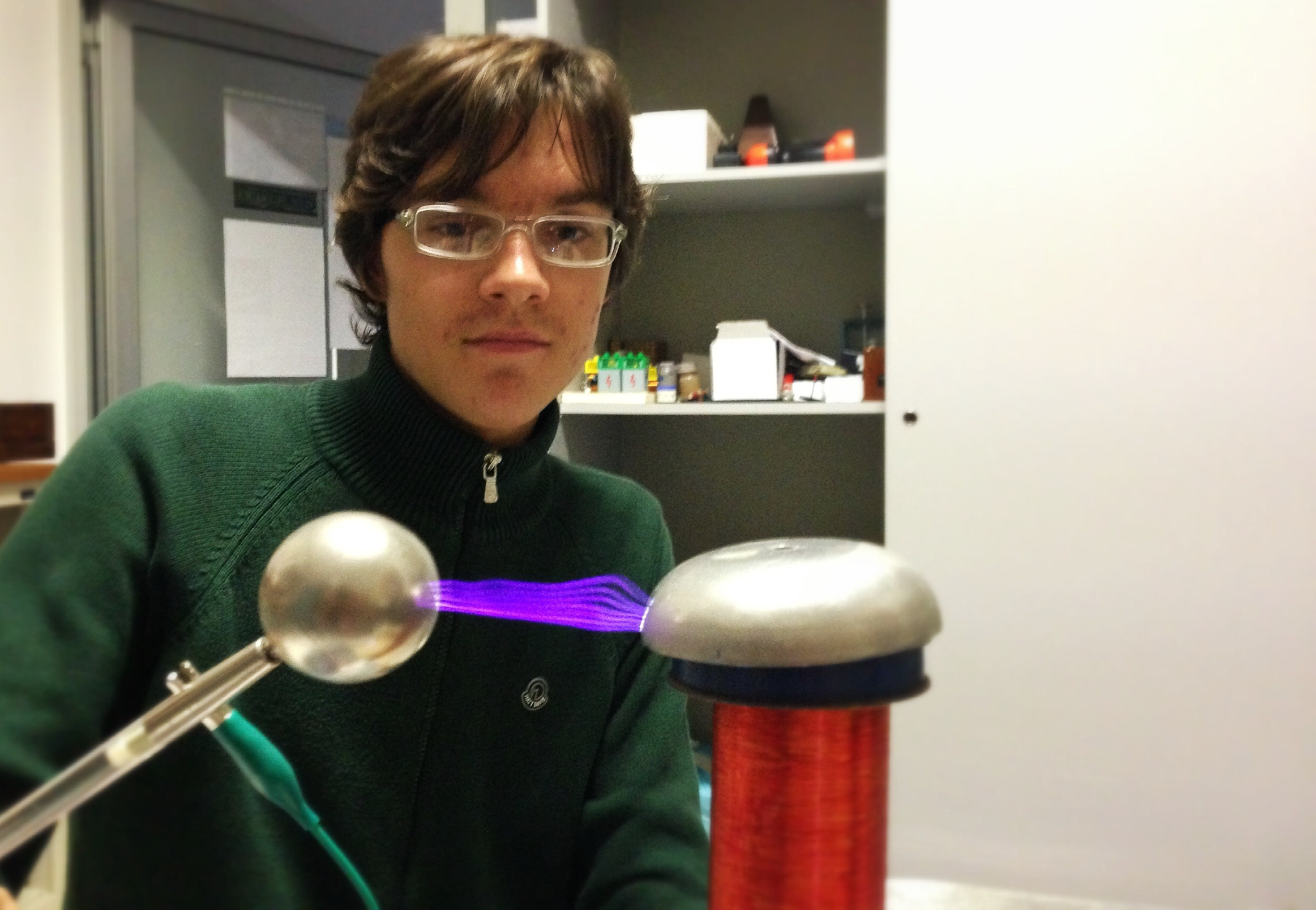
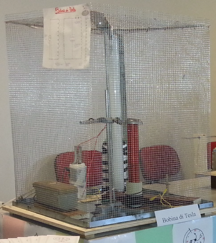
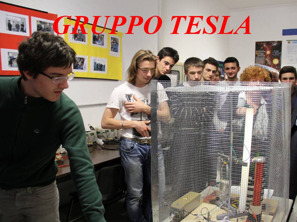
The Tesla Coil built by us
We used:
-A GENERATOR OF HIGH-VOLTAGE COIL A PRIMARY-SECONDARY COIL WITH TORUS-A CONDENSER FOR HIGH-VOLTAGE a spark gap
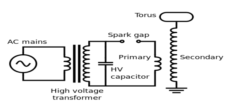
This is the circuit diagram:
High voltage generator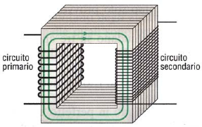
To build the generator I used a high voltage transformer for neon signs, it is a normal two-winding transformer with a laminated iron core. Features:-Primary circuit: 230V-secondary circuit: 3,500 V 35mA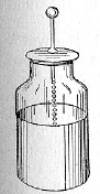 The transformer is a static electric machine (because it contains parts 6movimento) reversible, which serves to vary the voltage and current with constant power. The transformer is a machine able to operate only in alternating current, because it exploits the principles of electromagnetism variables related to the flows of the magnetic field. The voltage and amperage output depend on the ratio of the number of turns of the primary and secondary circuit, here’s an example: If the first coil consists of 100 turns were present in the second 1000 turns 10V and the voltage is 100V . So, the higher the ratio of the number of turns, the greater tension that it will have in the secondary coil.
For high voltage capacitor
We used a Leyden jar which typically consists of a glass container (for example a bottle) covered by a metal coating 7 on the outside and inside is a saline solution that will be the two armatures. In parallel to the high voltage generator 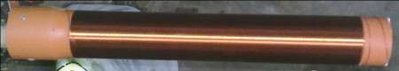 we hooked a Leyden jar, that by having a very low capacity but high voltage electrical work is the most ancient form of capacitor. The Leyden jar was used to conduct many early experiments with electricity during the second half of the eighteenth century. The Leyden jars have an electrical capacity rather low, which combined with high dielectric strength and thickness of the glass, making them ideal as capacitors for high voltage.
Spark gap
It is simply two screws spaced rounded head supported by two angular platelets.
Primary coil
To build it took the power cable cross section 0.5 cm2 wound on the outer surface of a tube about 8 cm high (no. of turns: 11).
Secondary coil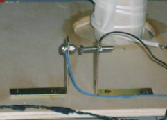
Made up of enameled wire of 1mm wrapped too ‘it on a pipe, a terminal is connected to the toroid on top of the coil, the’ other is grounded.
Operation
The Leyden jar capacitor is perfect for building an oscillator: The capacitor is charged by high voltage, and accumulates electric charge until it is sufficient to overcome the dielectric strength of the air between the electrodes of the spark gap of about 3 KV / mm. The main function of the oscillator is to “excite” electrically the primary coil of high frequency pulses, the energy is transferred from the primary coil to the secondary coil, a voltage that is obtained depends on the number of turns of the secondary and the frequency, and if very high, due to the formation of lightning that depart from the toroid place on top of the coil. While generating discharges, electrical energy is transferred to the surrounding torus. The electric currents that flow through these discharges are actually caused by the rapid change of the amount of charge from one point (the top terminal) to other places (nearby regions of air). The process is similar to a charge or discharge of a capacitor. The current that is created by the flow of charges within a capacitor is called displacement current. The discharge of Tesla coils are formed by a result of displacement currents as soon as the pulse of electric charges are rapidly transferred between the high voltage toroid and nearby regions of air (called regions of space charge). Although the space charge regions around the toroid are invisible, they have a fundamental role in the appearance and location of Tesla coil discharges. When the spark gap generates sparks, the charged capacitor discharges into the primary coils, causing oscillations in the primary circuit. The oscillating primary current creates a magnetic field which is coupled to the coils of the secondary transferring energy in the second part of the transformer and causing it to oscillate with the ability of the toroid. The transfer of energy takes place in a number of cycles, and most of the energy that was originally in the primary is transferred to the secondary. The larger the magnetic coupling between the coils, the shorter the time required to complete the transfer of energy. As the energy is formed inside of the secondary oscillating circuit, and the air surrounding the toroid begins to undergo dielectric breakdown, forming 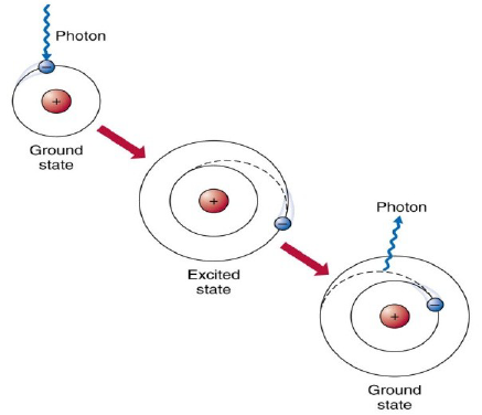 discharges. The induced current in the secondary coil in turn generates an electromagnetic field with frequency coupled with the primary, and this can cause the ionization of the surrounding air: you can experience this phenomenon approaching a fluorescent tube torus is seen to turn on without any electrical connection. When the neon atom is “excited” by a high-frequency one or more 10 electrons pass on the outer orbits with higher energy level of the atom. At this point the electrons unstable tend to return to their original orbits releasing the same amount of energy that had previously absorbed in the form of light. If current Tesla coils are used primarily to produce spark discharges (artificial lightning, electric arcs), the purpose for which they were designed was to generate streams of wireless energy transmission. The Tesla Coil although spectacular, because the propagation of electromagnetic waves at high frequency which can be very dangerous in the event of a ‘prolonged exposure (many years) with these radiations can cause cardiac arrest and also tumors. For this reason it is discussed how to make our experiment more secure and planned to use a grounded Faraday cage which prevents the leakage of electromagnetic waves by making the tesla coil 100% secure.
Leave a reply
You must be logged in to post a comment.