The Stirling Engine
Who’s Stirling?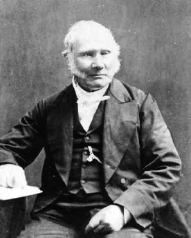
Robert Stirling (Methven, 25 October 1790 –Galston, 6 June 1878) was a Scottish protestant minister and the inventor of Stirling Engine. He inherited his father’s passion for engineering, but he studied theology at the university. Together with his brother James, engineer, Robert registered several additional patents to improve his own Stirling engine. The theoretical bases of this engine could not be completed and fully understood until the publication in 1825 of the studies of Sadi Carnot, who formulated the so called Carnot cycle, a general theory of thermodynamic engine of which Stirling cycle is an application.
Who’s Carnot?
Nicolas Léonard Sadi Carnot (Paris, 1 June 1796 – Paris, 24 August 1832) was French a physicist, engineer and mathematician. He is considered one of the founding fathers of thermodynamics. In 1824 he was the first to demonstrate that it is possible to obtain work from the exchange of heat between two sources at different temperatures. Through Carnot’s theorem and the ideal Carnot machine (based upon Carnot’s Cycle) he quantified this work and introduced the concept of thermodynamic efficiency. In 1848 Lord Kelvin, using the machine invented by the French physicist, introduced the concept of effective thermodynamic temperature and we owe to him a statement of the second principle of thermodynamics. In 1850 Joule demonstrated the equivalence of the two forms of energy (up to then, the existence of caloric fluid was still believed). The case of thermodynamics is emblematic: it is in facts one of those cases in which practice anticipated its own theory: first came the steam engine, then its theoretical principle of operation was systemized through its basic principles.
But, what is thermodynamics?
Thermodynamics is that branch of physics and chemistry that describes the transformations undergone by a system due to process that involve the transformation of mass and energy.
Why did Stirling build his engine?
Worried by the dangers to which workers in mines and foundries were subject, due to steam engines that often exploded because of the poor quality of cast iron boilers available at that time, he decided to improve the hot air machines hoping to find a safer alternative. The hot air engine could not explode, because it worked at a lower pressure and dangerous steam emissions where not possible. After a first successful phase of the Stirling engine, the enhancement of steam engines with more reliable materials made the Stirling less convenient and, due to its lower efficiency, its utilization was abandoned. Nevertheless, the engine invented by Stirling remains nowadays one of the most interesting and fascinating external combustion engines and it is still being studied, since the discover of new materials able to increase the temperature difference needed to its operation and the latest years environmental issues have triggered a new stimulus to realize new Stirling engines.
How does it work?
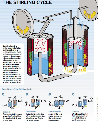
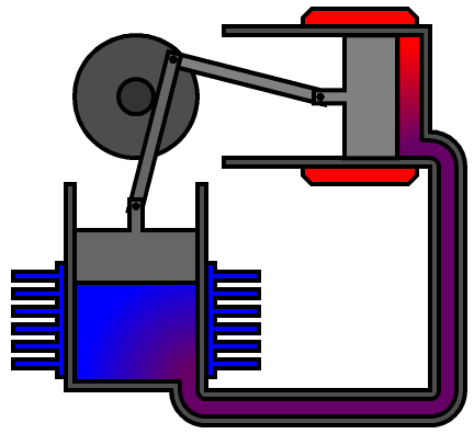
The engine works with a close cycle which utilizes a gas a thermodynamic fluid (usually air, nitrogen or helium and hydrogen in high efficiency versions). When a proper temperature difference between the hot and cold spots is reached and the motor is started, a cyclic pulse is triggered. This is transformed in alternate movement by the pistons. The motion continues as long as the temperature difference is kept constant providing heat to the hot point and removing it from the cold one. The only moving parts are the piston and the displacer, which operate connected one to the other by a crankshaft with two throws displaced one from the other by about 90 degrees. The Stirling engine requires reduced maintenance and the combustion is not related to any specific fuel. The needed temperature difference can also be generated using concentrated solar radiation heat The Stirling engine in Alfa configuration, as the model that we built, has a working principle possible easier to understand, and it’s based on 4 phases:  · push · heating · expansion · cooling In detail: PUSH PHASE:
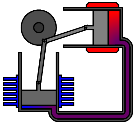
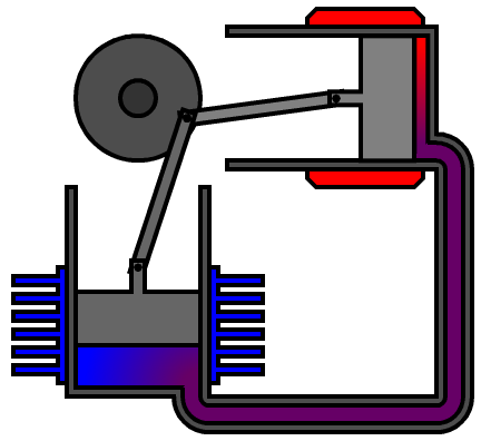
the number 1 piston (blue) pushes air towards the number 2 piston (red) placed above, which therefore moves letting the air in; HEATING PHASE: the air heats up, expands, and therefore comes back to the number 1 piston below, which moves;

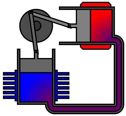
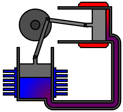
EXPANSION PHASE: the piston 1 movement lets the hot air get in contact with the heat sink (the fins around the piston 1). This way the air gets colder and therefore contracts, pushing the piston 2 towards the right; 
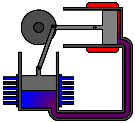
 COOLING PHASE: the movement to the right of piston 2, helped by the inertia accumulated by the fly-wheel, allows the shaft to continue its rotation. This pushes down the piston 1, blowing the air towards the piston 2 and restarting the cycle.
Il criterio innovatore di invenzione di Stirling del 1816, che ha reso possibile un utilizzo ragionevole del motore ad aria calda è il rigeneratore.
What is the regenerator?
A heat accumulator is placed in the alternate flux between the hot and cold spots, so to reduce the net loss of heat in the cold spot, where the heat is removed. This is the regenerator, which is made up by a small mass of a heat conductive material with a high exchange surface. This allows it to absorb a considerable amount of heat from the hot gas flux and, thanks to its small mass, to quickly increase its temperature. When the refrigerated gas flows back through the regenerator this gives back its heat to the gas, thus reducing its temperature. This makes the gas arrive back at the hot spot already pre-heated, thus drastically increasing the efficiency. In higher technology engines the regenerators are made of thin fins, metal wools or fine multi-layered metal meshes. The materials are usually inoxidizable and heat-resistant metals with high density and good heat conductivity: stainless steel, nickel or its alloys.
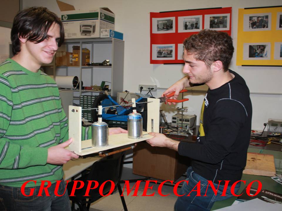
The design of our model:
Our target was to try to build the engine model using commonly available materials and elements. The design was initially done observing the various characteristics of the engine as illustrated in available images and from this we learned the basic components needed for the engine. We used: – two tomato soup cans; – two 33cl soda cans; – a 4 mm diameter iron rod (used to build the driveshaft); – two-component adhesive (NB: correggi in italiano, non è bicomponibile, è bicomponente!) – a 10 mm thick plywood board; – self-threading screws; – two iron clamps; – a 12 mm diameter u-shaped copper pipe; – linchpins. Initially we built the base of our engine cutting the plywood to a 180×500 mm rectangle, in which we made two holes of the same size of the tomato soup cans, so to wedge them in the wood surface. Then we created 185×75 mm frames for the driveshaft using the same 10 mm plywood and drilled in them an hole to allow the 4 mm rod through them. Before inserting the iron rod in the two holes, we bent it to form the couple of 90 degrees displaced throws. We then made holes in the tomato soup cans bottom to let the copper pipe through them and, once inserted, we glued them with the two-component adhesive (correggi anche qui in italiano, non “bicomponibile” ma “bicomponente”). Then we used the remainder of the plywood plank to build the two piston rods and we connected them to the 33 cl cans using linchpins. The cans top part had been previously cut in order for them to have an “overturned glass” shape, in order for them to contain the thermodynamic fluid (the air). Finally, we inserted the piston rods in the two crankshaft throws and we fixed the shaft in place using copper wire at its ends. The shaft supports were fixed to the wooden base with two metal clamps and self-threading screws.
Leave a reply
You must be logged in to post a comment.